Toolbox is a collection of several tools. The Toolbox contains a vast library of standard hardware components that can easily be dropped into an assembly. These components can be configured to populate BOM with part numbers, descriptions or other custom property. Toolbox is added with SolidWorks Professional and Premium. It is an Add-Ins.
But Toolbox should be set up to run properly.
Determining the location of Toolbox, network or locally.
Determining the location of Toolbox, network or locally.
If you have no intentions to do any changes with the toolbox and you do not have PDM, then it can be located locally at C:
If you are doing some changes on the toolbox, then it should be located on a server. By then can all users have the same files and settings.
PDM standard and PDM professional are built to manage toolbox and its files. It’s encouraged to install the toolbox in the PDM environment and setup the vault to manage the files within Toolbox.
If you have the Toolbox outside PDM, then you get a problem:
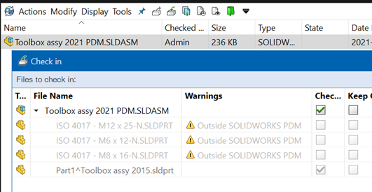
Shall I Check in Toolbox parts? This is not possible as long the Toolbox is outside PDM.
How will export of files with Copy Tree work? Without Toolbox parts inside PDM, will Copy Tree not add these Toolbox parts.
Installation
PDM standard and PDM professional are both built to manage SolidWorks toolbox and its files. It’s encouraged to install the toolbox in the PDM environment and setup the vault to manage the files within Toolbox. Details on how to this can be found in “Migrating Toolbox files to a network location or PDM Vault.”
Toolbox Installation
The SolidWorks toolbox is installed with every professional or premium version of SolidWorks. There are 2 different parts of the installation that deal with the toolbox.
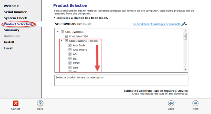
First is encountered in the Product Selection tab, in this window available standards can be excluded from the installation. By default, most users will leave all standards selected.
The second part of the installation that pertains to toolbox is the file location and file name of the toolbox. This is on the “Summary” tab in the installation window. By default, the toolbox is saved to the C:\ SOLIDWORKS Data. Both the location and name of the toolbox folder can be changed by simply selecting change. In the window that follows the user can select “browse” to change location and type in a folder name.
If you have multiple version of SolidWorks, is it recommended to also have a toolbox to each SolidWorks version. Name the Toolbox so it matches the SolidWorks version: C:\ SOLIDWORKS Data 2021.
It is a good idea to also name the installation of SolidWorks with the version year: C:\Program Files\SolidWorks 2021

Upgrade
When upgrading SolidWorks, it is recommended to use the installer to upgrade the toolbox automatically.
Pay attention to what you will do with the toolbox when you upgrade SolidWorks. You can upgrade an existing Toolbox or make a new Toolbox. If you have not made any changes on the Toolbox, is it best to make a new one.
The first to upgrade SolidWorks shall also upgrade Toolbox, if it is located on the server. If it is located in the PDM vault, check out all files, upgrade and check in again.
If the automatic update is not working, will you get a warning like this.
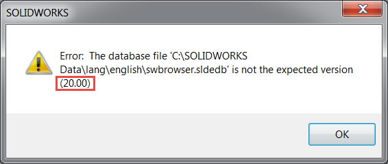
18.00 corresponds to SOLIDWORKS 2015
19.00 corresponds to SOLIDWORKS 2016
20.00 corresponds to SOLIDWORKS 2017
21.00 corresponds to SOLIDWORKS 2018
22.00 corresponds to SOLIDWORKS 2019
23.00 corresponds to SOLIDWORKS 2020
24.00 corresponds to SOLIDWORKS 2021
The version (Year and Service Pack) of toolbox is also written in the file ToolboxVersion.dat under the Toolbox folder: C:\SOLIDWORKS Data
Before upgrading the toolbox, it is recommended that a back-up is made. Make a copy of the toolbox folder and moving that copy to a safe location. A suggestion is to right click on the folder and choose Send to > zip. This will create a zip copy of the folder in its current state. PDM users this step isn’t required since previous versions of the database are indexed in the vault and can be rolled back.
Now need to navigate to:
C:\Program Files\SolidWorks 2021\SOLIDWORKS\toolbox\data utilities\ UpdateBrowserDatabase.exe
Right click UpdateBrowserDatabase.exe and run as Administrator.
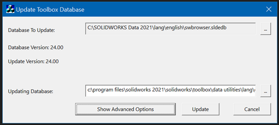
If Database Version and Update Version is the same, then the Toolbox is updated.
If Toolbox is located in PDM, is it recommended to check out the hole Toolbox.
Check out at least the database file swbrowser.sldedb. In the case a file named swbrowser.sldedbold is also found in the directory it will need to be checked out as well.
Run the update utility it’ll take several minutes. Once this is complete the toolbox will be updated. Test functionality by launching the toolbox inside of Solidworks.
After the update check-in the database and have users get latest so the changes are reflected for all users.
Toolbox setup
This is the first setup:
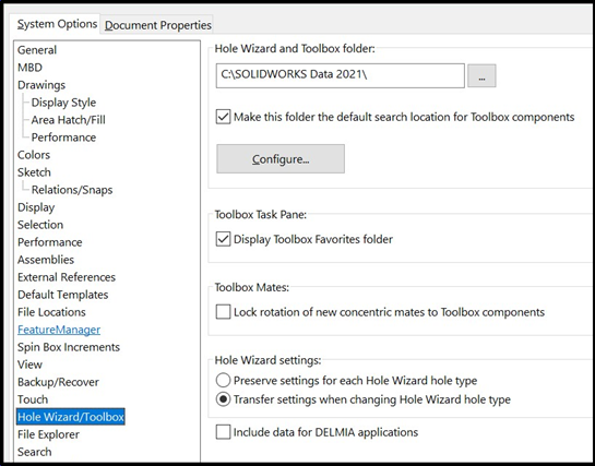
Make this folder the default search location for Toolbox components.
If you clear the system option, SOLIDWORKS does not automatically search the Toolbox folder for references to Toolbox components.
If this setting is on, Then SolidWorks will replace Toolbox component from an imported assembly with the component you have in your Toolbox. The path to the components will be changed to your Toolbox and the path will not be to the components following the imported assembly. That mean if you have part numbers to the components, then you will get yours part numbers on the components. And you will only have one set of components. This is in many ways recommended.
If you get trouble by importing of assembly with toolbox components, then this can be because you do not have that specific component in your Toolbox. Try to put these missing components into the Toolbox or turn off: Make this folder the default search location for Toolbox components.
Click on Configuration and tab 3 – User settings. Then you will get this picture:
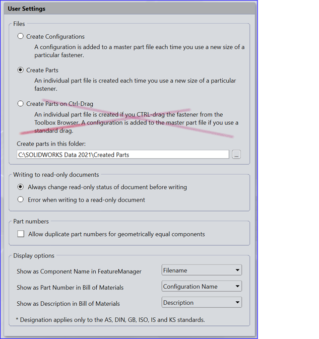
Create Configurations
The ‘Create Configurations’ option is active by default. However, this does not mean that the setting is superior to the ‘Create Parts’ option. The ‘Create Configurations’ option causes new configurations to be made within a given master part file for each variant of a particular Toolbox part. For example, if the master part file is ‘socket button head cap screw_ai.sldprt’, then all of the different sizes of the screw that a user chooses to use will result in new configurations getting stored in that single part file. This results in the creation of fewer individual files and therefore fewer files that a user needs to keep track of. However, for Toolbox components where many different sizes are used, the size of master part file will grow over time.
Create Parts
The ‘Create Parts’ option results in individual part files of a smaller size because each variant of a particular part is saved as a uniquely named part file that contains just one configuration. Some customers prefer to have the one-to-one relationship between part numbers and files. However, the ‘Create Parts’ option creates many more individual files when compared to the ‘Create Configurations’ option. In some technical support situations, it is easier to troubleshoot assembly reference issues that relate to Toolbox parts when using the ‘Create Parts’ option. This is because this option removes the variable about whether the correct configuration is being referenced.
Create Parts will do so big assembly with many Toolbox parts run faster.
Set up where you wish to store the parts in the settings: Create parts in this folder. This should be inside the Toolbox folder. If SolidWorks can’t find a Toolbox part, it will search in the Toolbox folder.
Note: As a best practice, do not switch between the ‘Create Parts’ and ‘Create Configurations’ options without careful testing.
We recommend that you do not use the ‘Create Parts on Ctrl+Drag’ option. This option can result in inconsistent use of hardware within the company.
Disabling content and sizes
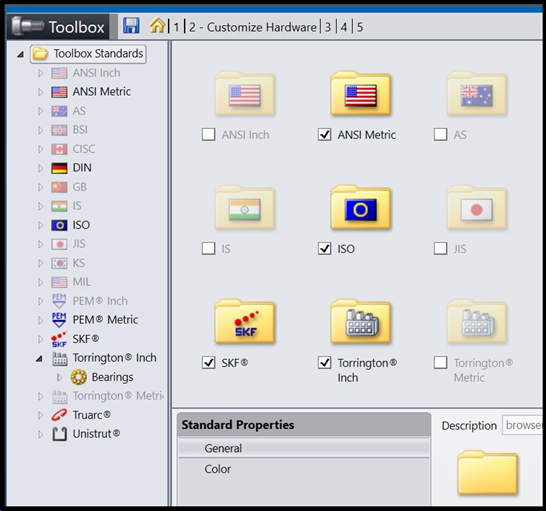
The Toolbox has the potential to produce is very large number of hardware variants. For example, ‘ANSI Inch’ socket head cap screw, it is possible to produce a default total of 32,988 configurations. If you add other user defined custom properties; that number multiplies. When designing for manufacturing and purchasing efficiency, users should not have access to all of the hardware that the Toolbox can potentially produce. To reduce the use of undesired hardware, you should limit the standards, hardware, sizes, and variants to which users have access.
Before implementing the Toolbox in a customer’s production environment, the CAD Administrator can use the ‘Toolbox Settings’ tool to limit the hardware selection. The “Standard Properties” (diameters, lengths, pitches, thread representations, drive types, etc.) vary for each Toolbox part. With input from Engineering, Manufacturing, and Purchasing, the CAD Administrator can disable the standards, parts, sizes, and geometry variants that they do not want the users to access. The following image depicts the area of the ‘Toolbox Settings’ tool that allows the CAD Administrator to do this tuning.
A company should develop an internal process for requesting enablement of hardware in the event a user needs a particular piece of Toolbox hardware that is disabled. The limiting of the hardware choices should be done prior to assigning Part Numbers and Descriptions.
Permissions
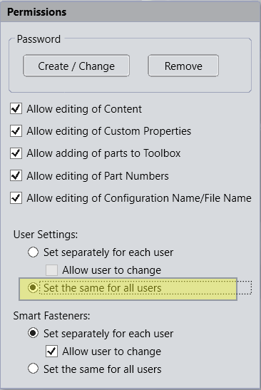
For a multi-user Toolbox environment, the CAD Administrator should use the ‘Permissions’ section of the ‘Toolbox Settings’ tool to enable permission controls. The following image shows the ‘Permission’ interface with the default settings. A customer needs to determine which options they need for their use case. Usually, this means disabling certain permissions in the interest of limiting the hardware that the users can generate. The CAD Administrator should disable sizes and standards that they do not use. This prevents designers from adding fasteners that are not standard.
When managing the Toolbox in a SOLIDWORKS PDM vault, it is especially important to set the ‘Set the same for all users” option. This option prevents the possibility of some users running in the ‘Create Parts’ mode, and others running in ‘Create Configurations’ mode.
A wired connection will usually be much faster than a wireless connection. The same is true if users connect over a virtual private network (VPN) or another remote connection type. As part file sizes increase, there will likely be certain limitations.
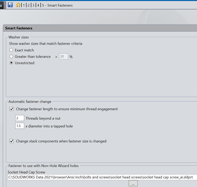
Smart fasteners
The settings for the smart fastener can also be found in toolbox settings, they’re under tab5 Smart Fasteners This is portion will outline the settings found here and how they’ll effect the use of smart fasteners inside SolidWorks. There are 3 sections to the settings in the smart fasteners menu.
- Washer sizes: this will determine the size of washer used when inserting washers into a top stack.
- Automatic fastener change: Hardware lengths are automatically calculated when inserting hardware using smart features, these rules dictate the length of those components.
- Non-hole wizard holes: the smart fastener is built to work with hole wizard holes, it’s possible however to manually choose generic holes in an assembly and smart fastener will populate the default fastener listed in this window.
Toolbox Functionality
The toolbox has many different options for adding hardware into assemblies, the two most common methods what will be covered in this manual are drag & drop, along with the use of smart fasteners. Other methods are within smart components, smart features, and the hole series commands.
Enabling Toolbox Add-in
To utilize the toolbox the feature will first need to be enabled inside of SolidWorks this can be done on an as needed basis or can be configured to automatically start when the program launches.
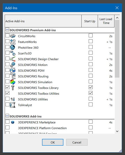
SOLIDWORKS Toolbox Library loads the Toolbox configuration tool and the Toolbox Design Library task pane, where you can access Toolbox components.
SOLIDWORKS Toolbox Utilities loads Beam Calculator, Bearing Calculator, and the tools for creating cams, grooves, and structural steel.
ToolboxFiles.index
Tis is located in the folder browser. This file serves as an index or cache for a variety of settings that are stored within each Toolbox file. Any changes (customizations) that you make to the Toolbox structure are stored in the ‘ToolboxFiles.index’ file. When you open the Toolbox, the software searches this file to determine what standards, categories, types, or components are enabled. Objects that you enable are made available to users. To save the Toolbox settings, you must have ‘write’ permissions to the ToolboxFiles.index file.
Updates folder
The ‘Updates’ folder serves as a record of the update history for your Toolbox data set. The SOLIDWORKS software accesses this folder every time you run an update on the system. The folder contains a number of Toolbox files that SOLIDWORKS creates or references during an update. These are proprietary and you should never edit them. The filenames contain an internal version number that relates to the major SOLIDWORKS version on which they are created. For example:
2300_Install ISO.tbox corresponds to SOLIDWORKS 2020
2400_Install DIN.tbox corresponds to SOLIDWORKS 2021
The ‘Updates’ folder also contains the update log file with the name ‘UpdateLog.txt’. This log records a description and date of each update. The log also includes specific errors that are useful when troubleshooting problems with Toolbox updates.
ToolboxStandards.xml
This file is created during the installation of SOLIDWORKS. The Installation Manager allows users to define which Toolbox standards are installed so that the Toolbox data is easier to manage. Users are able to “turn-on/ turn–off” standards in this way. Choices made in this process are written to this ToolboxStandards.xml file. Standards marked as ‘<Install>NO’ will be ignored during the upgrade process. Examining this file can be helpful when investigating why a standard is missing or has not been updated.
Adding Content
Customers can add parts to the Toolbox by right-clicking on a folder in the ‘Toolbox Settings’ tree, and then selecting the ‘Add File’ option.
It is important to note that adding user created files to the Toolbox will have some primary behavior differences compared to native Toolbox parts. When inserting a user made Toolbox part into an assembly, the ‘Configure Component’ PropertyManager will present a list of existing configurations from which to choose. However, there are no drop-down menus to select different dimensions or values that drive part geometry. In addition, in the ‘Toolbox Settings’ interface for that component, there is no configuration table that displays part numbers and descriptions.
When inserting parts into an assembly, you can use the SOLIDWORKS ‘Configuration Publisher’ functionality (not part of Toolbox) to generate a user interface in the ProgramManager that is similar to the Toolbox. However, such content does not work with Smart Fasteners.
In the Toolbox Design Library, user created content displays a “blue torso” icon next to the parts, as shown in the next image. These blue icons help users easily differentiate between standard components and components added by users. The SOLIDWORKS 2015 software is the first version that can show this icon. The icon will only appear in SOLIDWORKS 2015 or later files. For this reason, legacy file icons remain untouched.
Author
Jan Egil Bæver
Kommentarer
Log ind for at kommentere.